Using a webcam with OpenCV to display video on an LED Matrix controlled by arduino
06 Dec 2009Recently I’ve been looking for new things to do with my LED Matrix shield I made for arduino and as I have some experience with writing video caputure systems I thought I’d have a go at trying to capture webcam video frames and processing them and then displaying them in real time on an 8x8 LED Matrix. Previously as part of my masters thesis I had worked with OpenCV which, amongst many other image processing and computer vision features, provides simple, cross platform video capture capability so this formed the starting point of my experiments.
In this post I will describe a method for the capture of video frames from a webcam using OpenCV, the subsequent processing required to convert to an 8x8 monochrome image and the process of sending the data via serial to arduino using libserial which is linux specific. Example source code is included at the end.
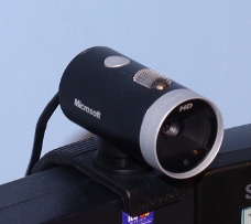
Having previously used a Logitech Quickcam Fusion with windows and OpenCV I started out on this project assuming it would work in linux, however the camera isn't fully supported by Linux due to the specific chipset used so I replaced my webcam and found the Microsoft Lifecam Cinema Webcam to be fully linux compatible and the highest quality webcam currently available at a sensible price (currently ~£45 on Amazon) and has proved to work very well in all respects producing very high quality images (for a webcam).

Video Capture and Processing
The rest of this post assumes that OpenCV has been correctly installed and is known to the compiler and will concentrate on the main functions required to perform the capture and image processing. OpenCV represents video streams as CvCapture objects, andOpenCV images such as video frames as IPL images, a standard type defined by Intel but basically an encapsulated BGR matrix of the pixels. So initially I define the variables which will hold the capture stream and the images required:CvCapture * pCapture; //new OpenCV capture stream
IplImage * pVideoFrame; //new OpenCV image
IplImage * pVideoFrameBW; //new OpenCV image for colour conversionpCapture = cvCaptureFromCAM(0); //choose camera for capturecvNamedWindow( "video", CV_WINDOW_AUTOSIZE );cvWaitKey(int time) function which returns -1 if no key press has been detected and the ASCII code of the character if a key is pressed within the time specified in milliseconds. Therefore the main loop will be of the form:
int key = -1;
while(key==-1)
{
capture and process
}
clean up and exitcvQueryFrame(CvCapture pCapture) method:
pVideoFrame = cvQueryFrame(pCapture);cvThreshold(pVideoFrame, pVideoFrame, thresh, 255, CV_THRESH_BINARY); thresh is the level to which thresholding is required, more information can be found here.
As the data required for display on a basic LED matrix is not in colour it needs to be converted to black and white, in OpenCV this works by creating an empty image of the correct colour depth and then using the cvCvtColor() function:
pVideoFrameBW=cvCreateImage(cvGetSize(pVideoFrame),8,1);
cvCvtColor(pVideoFrame, pVideoFrameBW, CV_BGR2GRAY);/*create small image*/
IplImage* out = cvCreateImage( cvSize(pVideoFrameBW->width/60,
pVideoFrameBW->height/60), pVideoFrameBW->depth,
pVideoFrameBW->nChannels );
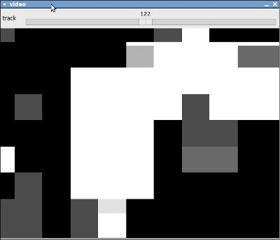
cvResize(pVideoFrameBW,out,CV_INTER_NN); cvResize(out,pVideoFrameBW,CV_INTER_NN);
cvShowImage( "video", pVideoFrameBW);for(int y=0; y<8; y++)
{
for(int x=0;x<8;x++)
{
CvScalar s;
s=cvGet2D(out,y,x);
/*save pixel value (blue)*/
int p = s.val[0];
/*print value to terminal for debugging*/
printf("%i",p);
if(p==255) //if the pixel is black
{
p=1; //turn on led
}
}key = cvWaitKey(20);
/*release memory*/
cvReleaseImage(&pVideoFrameBW);
cvReleaseImage(&out);cvReleaseImage( &pVideoFrame );
cvReleaseCapture ( &pCapture );
cvDestroyWindow( "video" );